
Arterial lines can provide accurate, real-time information on your patient’s blood pressure. They can be vital in cases where you want to trend precise blood pressure goals or where BP cuffs are producing incongruous measurements in a critically ill patient. However, as with all tools the information they yield is only as good as the assay you use to measure it. As with all tests, arterial line measurements can be prone to error. In order to optimize your arterial line and receive accurate data it helps to know how it works.
The line itself is composed of hydraulic and electrical systems that work together to produce a pressure waveform on your monitor. The hydraulic system is composed of the vascular catheter itself, hollow fluid filled IV tubing, stopcocks to permit flow to be diverted, a continuous flush device to provide constant low grade flow to keep the line clear, and a pressure transducer. A series of fluid (typically saline) filled tubed connects from the arterial catheter to the pressure transducer forming an unbroken column of fluid contiguous with your patient’s arterial vasculature. The pressure transducer is typically a silicone diaphragm and operates in conjunction with a system of 4 resistors known as a wheatstone bridge. In this system three resistors generate pre-determined resistance to an electrical current while the fourth is “zeroed” at this value and subsequently varies according to the deviation in resistance from this set zero point. The variable resistance is provided by the silicone diaphragm and the resistance of the circuit varies proportionally to pressure applied to this diaphragm. The change in voltage is measured and reported by a voltmeter within the circuit. You should know how to set this system up prior to starting critical care shifts: for an excellent tutorial on how to set such a system up see the linked videos below on ECHED.org. The pressure transducer will typically come pre-assembled for you. Some elements of these videos are specific to Elmhurst hospital and to the emergency departments’ website on which they are hosted.
http://ehced.org/set-up-a-
http://emcrit.org/pressure-

A Wheatstone Bridge. The variable resistor is indicated by the arrow at R2.
The electrical system for the line consists of an amplifier, a monitor/oscilloscope, a processor, and a recorder. The amplifier will take the voltage reported by the pressure transducer and convert it into a visible signal. The monitor or oscilloscope displays this signal for your review. The processor will take this data and calculate hemodynamic parameters. Your recorder will store and print this data. Of the two systems, the hydraulic system is more likely to suffer errors that your are able to fix or optimize than the electrical system.
The relative altitude of your pressure transducer and the stopcock to your patient’s heart when the system is zeroed can affect the values reported by the transducer. Changes in altitude lead to common errors in measurement. When the transducer/stopcock is placed properly it is said to be aligned with the body’s “phlebostatic axis.” The appropriate point can be determined by drawing a line through the 4th intercostal space and locating the spot at which it intersects with the mid axillary line which will zero the system to the level of the right atrium. The stopcock that you use to set the “zero” point for the system is the actual determinant for the zero pressure experienced by the transducer. Some transducers will come with a stopcock attached at the end, however if this is not the case or if you choose to use a different stopcock then this point will determine the altitude experienced by the transducer and should be taped to the patient’s chest at the phlebostatic axis to ensure its accuracy. The system is zeroed by turning the stopcock open to air (and closed to the patient) and then hitting the zero button on your monitor. This location of the phlebostatic axis (as an approximation of the right atrium) is chosen because this describes cardiac pre-load. Positioning the transducer lower than this point will report falsely elevated pressures due to increased pressure applied to the hydraulic tubing. If the transducer is positioned above the phlebostatic axis then the pressure applied to the tubing will be lower and will yield falsely low blood pressure readings. Depending on the indication for invasive monitoring, you may be most interested in different reference points and the transducer altitude may be adjusted accordingly. For example, in a patient in whom intracranial arterial pressures are of chief interest the pressure transducer may be set at the level of the eternal auditory meatus and will reports pressure with reference to that point.
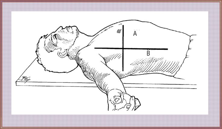
The phlebostatic axis.
Tomorrow’s pearl will continue to explore optimization of your arterial line and troubleshooting more complex errors.
Cheatham ML. Hemodynamic Monitoring: Principles to practice. http://sinaiem.org/wp-content/uploads/2016/05/ABP-photo.jpghttp://www.surgicalcriticalcare.net/Lectures/PDF/hemodynamic%20monitoring%20principles%20to%20practice.pdf. Updated 1/13/2009. Accessed 5/2/15.
Rhdv – Own work, CC BY-SA 3.0, https://commons.wikimedia.org/w/index.php?curid=2888809
